Motor Roller Unit
- Lineup
- Functions and application examples
Features
Freely control operation, stopping, etc.
It can be operated continuously or intermittently, and the conveying direction can be freely controlled in both forward and reverse directions.
Quiet and stable rotation speed
It achieves stable transport within the allowable load, and also rotates smoothly with low noise.
One-touch installation type
The one-touch mechanism makes it easy to attach and remove from the frame. (This does not apply to some models.)
Easy line design
It is easy to incorporate into a line, reduces the labor required for line design, standardizes the line design, and makes it easy to build an automated conveying line.
No need for oiling, hygienic
No need for oiling, so it is hygienic and requires little maintenance.
RoHS compliant
This conveyor uses materials that comply with the RoHS Directive, making it environmentally friendly.
Model and specification list
Motor roller model examples and model code explanations
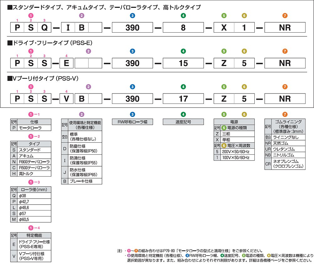
Specification environment (various specifications)
 D: Dustproof (protection class IP50)
We recommend the dustproof version for environments with a lot of small particles and dust.
*Standard lead wire length: 150mm
 I: Water-proof (protection class IP55)
We recommend the waterproof model for conveying lines that involve moisture, dusty locations, and locations where small amounts of water droplets may fall.
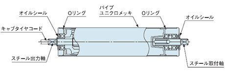
| Material | |||
|---|---|---|---|
| Roller Pipe | Mounting shaft | Output shaft | Mounting bracket |
| steel | steel | steel | SUS304 |
Notes: ①The output shaft of PSP-I only is made of SUS303.
②In addition to the standard material, stainless steel specifications are also available.
※ローラパイプ、シャフトはスチール製です。
※最小寸法およびワンタッチ取付機構の有無は各機種ページをご参照ください。
※キャブタイヤコード長さ:単品出荷時300mm、組み込み出荷時2000mm
 J: Waterproof (protection class IP65)
We recommend waterproof specifications for places where water may come into contact, such as cleaning lines and outdoors.
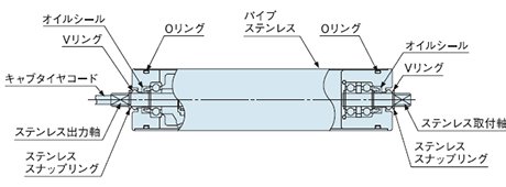
| Material | |||
|---|---|---|---|
| Roller Pipe | Mounting shaft | Output shaft | Mounting bracket |
| SUS304 | SUS303 | SUS303 | SUS304 |
*The tangential force of the waterproof model is 20% lower than that of the standard model.
※ローラパイプ、シャフトはステンレス製です。
※ワンタッチ取付機構はφ38、φ42.7、φ48.6のみ標準仕様です。φ57、φ60.5には適用しません。
※最小寸法は各機種ページをご参照ください。
※キャブタイヤコード長さ:単品出荷時300mm、組み込み出荷時2000mm
Special function rubber lining (various specifications)
 B: Brake specifications
It is equipped with a dedicated electromagnetic brake that opens when energized, so we recommend the brake specification when stopping precision is required or when you want to hold the stopped position.
- The brake power supply is the same as the motor power supply.
・The inverter is only compatible with motor roller power supplies: 200V three-phase.
- When using an inverter, separate the brake lead wire from the motor circuit and control it on the primary side.
・Please refer to each model page for brake power consumption (W), current (A) and brake torque (N・m).
 NR, UR, NB, CR: Rubber lining specifications
We recommend using a rubber lining to prevent lightweight items from slipping and to protect the transported items.
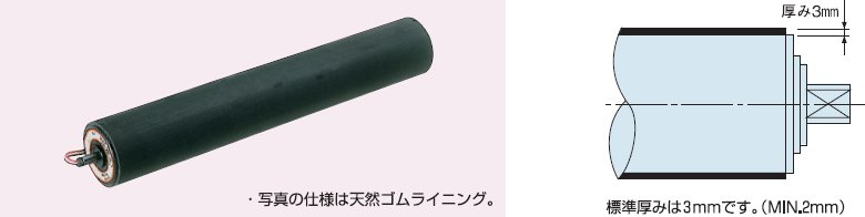
| symbol | Types of rubber lining | Purpose | Note | color |
|---|---|---|---|---|
| NR | natural rubber | General use | Weak to oil | black |
| UR | Urethane rubber (ether type) | Abrasion resistance | Heat-sensitive | No coloring |
| NB | Nitrile rubber | Oil resistance | Weak against benzene and toluene | black |
| CR | Neoprene rubber (chloroprene rubber) | Heat and chemical resistance | Weak against ethyl acetate | black |
- The standard thickness of the lining is 3mm.
・For rubber lining specifications other than those listed above, please contact our sales department.
Mounting bracket/mounting method
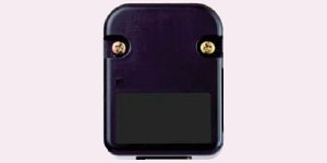
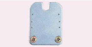
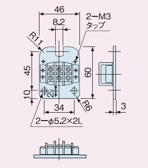
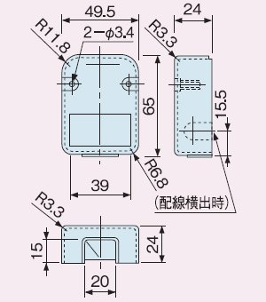
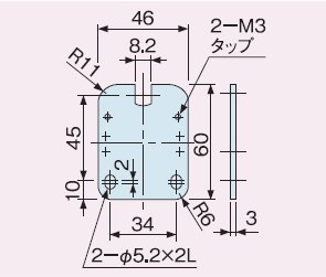
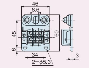
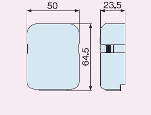
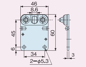
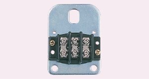
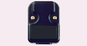
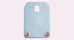
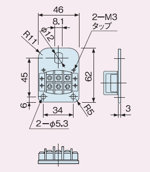
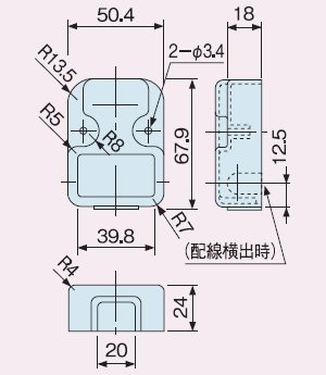
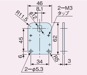
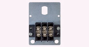
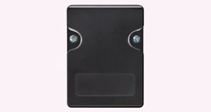
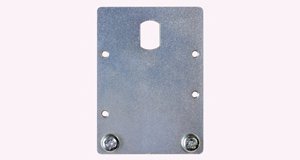
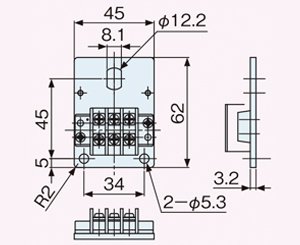
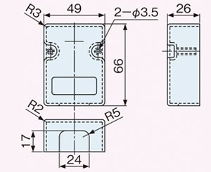
Terminal block, terminal block cover, anti-rotation bracket
| φ38.0 | ||
|---|---|---|
| terminal block | Terminal block cover | Anti-rotation bracket |
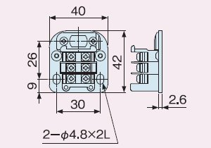 |
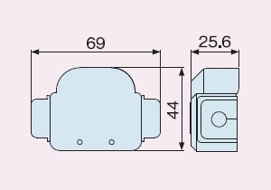 |
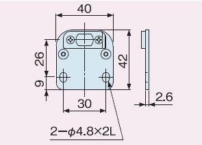 |
| φ42.7 | ||
|---|---|---|
| terminal block | Terminal block cover | Anti-rotation bracket |
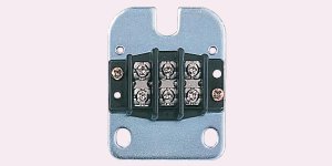 |
 |
 |
 |
 |
 |
| φ48.6 | ||
|---|---|---|
| terminal block | Terminal block cover | Anti-rotation bracket |
 |
 |
 |
| φ57 (excluding PSS-V) / φ60.5 | ||
|---|---|---|
| terminal block | Terminal block cover | Anti-rotation bracket |
 |
 |
 |
 |
 |
 |
| φ57 PSS-V | ||
|---|---|---|
| terminal block | Terminal block cover | Anti-rotation bracket |
 |
 |
 |
 |
 |
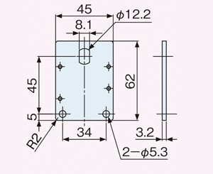 |
- Fix the motor roller output shaft to the frame with a dedicated terminal block and anti-rotation bracket.
If the output shaft spins freely, the lead wire may break, causing a malfunction. - The motor roller includes the standard terminal block, terminal block cover, and anti-rotation bracket shown above.
However, the following cases are exceptions.
①D: Dustproof, I: Drip-proof, J: Waterproof specifications do not have terminal blocks.
②B: Brake specification, PSS-E: Drive-free specification require a separate terminal block.
Please contact our sales department for details. - Even with drip-proof or waterproof specifications, dust can accumulate on the live parts of the motor rollers and on the connecting parts of the jumper wiring.
If water gets on the wires, there is a risk of short circuit, leakage, electric shock, fire, etc., so be sure to connect the wires securely. - The shaft hole of the φ38 terminal block and anti-rotation bracket faces sideways.
Motor roller installation method (one-touch installation mechanism)
The shaft is recessed, allowing for one-touch installation and removal.
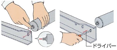
- If the motor roller pipe and shaft have the same diameter as the free roller, the shaft hole of the free roller can be used as is.
- If the dimensions are different, change the frame shaft hole to match the height of the free roller so that the load is distributed evenly.
- If the bottom of the transported item does not come into contact with the motor rollers due to the material or smoothness of the transported item, use at least two motor rollers per case. Or set them slightly higher. In this case, the load will be borne by the motor rollers alone, so please pay close attention to the allowable load of the motor rollers.
- Depending on the specifications, the one-touch mounting mechanism may not be compatible.
Handling Precautions
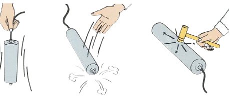
Please be careful not to carry the product by its lead wires, or to bump or drop it, as this may damage the internal parts. Also, when passing the lead wires through the frame holes, be careful not to damage the insulation.
Wiring example
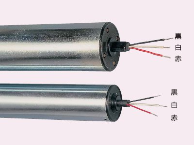
- The motor roller's power supply lead wires are three wires: black, white, and red (however, brake specifications or PSS-E: drive-free type have five wires). The direction of rotation can be changed by swapping two of the three lead wires. When using multiple motor rollers, the rotation direction will be the same if all the lead wires are connected in the same way.
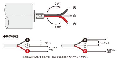
- For dustproof, drip-proof, waterproof, and brake specifications, and for PSS-E: drive-free, the wiring examples and connection methods will differ from those shown below. Please contact our sales department for details.
100V single-phase wiring example (external capacitor installation)

- This applies to all Motor Roller Conveyor with standard 100V single-phase specifications.
- The capacitor is attached to the side of the terminal block using double-sided tape.
- The crossover wiring cable used is SVCT0.75Sq*3C.
- For PSP etc. φ42.7, up to 40 wires can be connected in series, and for PSS etc. φ57, up to 20 wires can be connected in series. However, the total length per system must be up to 60m.
- When using reversible operation on the primary side of the crossover wiring, if one wire fails, the capacitor balance will be lost, causing failure of other motor rollers or causing rotation problems, so please be careful.
200V three-phase wiring example
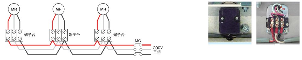
- This applies to all Motor Roller Conveyor with standard 200V three-phase specifications.
- The crossover wiring cable used is SVCT0.75Sq*3C.
- For PSP etc. φ42.7, up to 40 wires can be connected in series, and for PSS etc. φ57, up to 20 wires can be connected in series. However, the total length per system must be up to 60m.
- If you use an inverter, use the MC as the inverter.
Application example
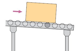
- Self-propelled line (braking and restarting)
-
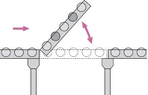
- Drive roller lifting device
-
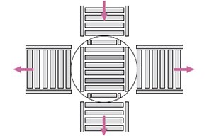
- Attach it to the top of the turntable
Branching device -
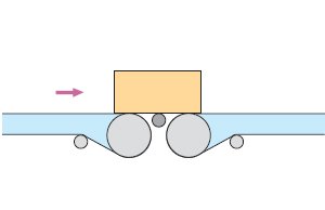
- Belt conveyors and slat conveyors
Joint -
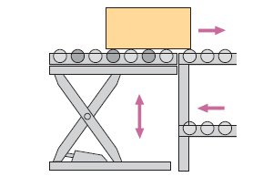
- Combination with table lifter
-
- Right-angle turntable
-