HOME > Product Information > Conveyor Equipment > Light Conveyor > Magnetic Drive Conveyor > Magnetic Drive Conveyor / MFS
Magnetic Drive ConveyorMFS
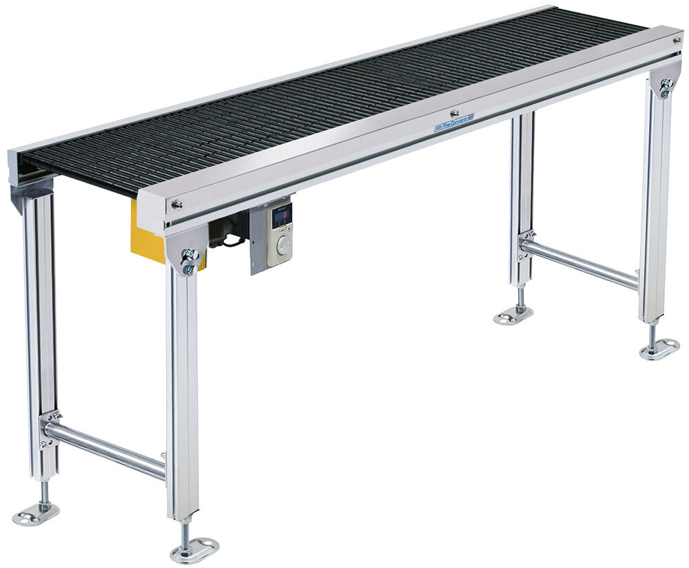
Accumulation type (resin roller)
Aluminum frame accumulation conveyor


About the various icons
- Web Catalog
-
- *Please contact us separately for guides.
specification
 MFS |
 30 |
 D |
 L |
 200 |
 D15 |
 L |
 09 |
 X |
*Colored text is semi-standard.
|
Model code | MFS (accumulator type) | |||||||||
|---|---|---|---|---|---|---|---|---|---|---|---|
|
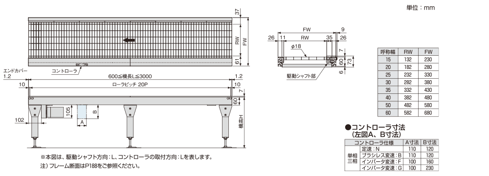
Nominal width | 15 | 20 | 25 | 30 | 35 | 40 | 50 | 60 | ||
| RW Actual roller width (mm) | 132 | 182 | 232 | 282 | 332 | 382 | 482 | 582 | |||
| FW Frame width (mm) | 230 | 280 | 330 | 380 | 430 | 480 | 580 | 680 | |||
|
L Captain (cm) *1 | MIN.60〜MAX.300 | |||||||||
| Carrier Roller Diameter | φ18 | ||||||||||
| Roller pitch (mm) | 20 | ||||||||||
| Roller Material | Black Resin | ||||||||||
|
Drive Type | D: Subscript | |||||||||
|
Drive shaft direction *2 | R: Right side L: Left side | |||||||||
|
Speed symbol | Please refer to the "Speed Symbol/Conveyor Speed Table" | |||||||||
|
Controller installation direction *2 | R: Right side L: Left side | |||||||||
|
Motor Output | N: constant speed | 02:25W 04:40W 06:60W 09:90W | ||||||||
| D:ブラシレス変速 | 05:50W 09:90W | ||||||||||
| F:インバータ変速 | 02:25W 04:40W 06:60W 09:90W | ||||||||||
|
Input Power | X: 100V single phase Y: 200V single phase Z: 200V three phase | |||||||||
- The length is measured in 20cm increments.
- Please refer to "Drive shaft direction/controller installation direction."
- Do not use the unit when it is out of step.
- Do not use in dusty environments or in environments where water, oil, etc. may be present.
- Overhanging transport is not possible.
- If you are using a pacemaker or other medical device, please do not go near the magnet as it may affect your health.
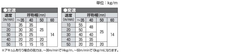
Conveying capacity guideline
Motor output setting guideline

- May vary depending on the items being transported, specifications, and conditions.
For details, please contact our sales department.
Speed symbol/Conveyor speed table
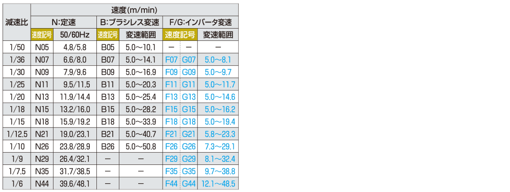
- 1. 色文字 は準標準速度を表します。
2.定速とインバータ変速の速度は、負荷により±10%程度変動します。
3.ブラシレス変速時の負荷による速度変動は±1%以内です。
Drive shaft direction/controller installation direction
