Jabcon IIJHG 90W
ヘッドドライブ 蛇行レスタイプ
〈インダクションモータ〉
The head drive structure prevents meandering. Reliable transport even under harsh transport conditions.




About the various icons
specification
 JHG |
 30 |
 H |
 R |
 300 |
 F13 |
 L |
 09 |
 X |
*Colored text is semi-standard.
|
Model code | JHG (Head drive, meander-less) | |||||||||
|---|---|---|---|---|---|---|---|---|---|---|---|
|
Nominal width | 10 | 15 | 20 | 25 | 30 | 35 | 40 | 50 | 60 | |
| BW Actual belt width (mm) | 95 | 145 | 195 | 245 | 295 | 345 | 395 | 495 | 595 | ||
| FW Frame width (mm) | 145 | 195 | 245 | 295 | 345 | 395 | 445 | 545 | 645 | ||
|
Captain (cm) | Nominal width 10 to 50: MIN. 100 to MAX. 400 Nominal width 60: MIN.120 - MAX.400 |
|||||||||
| Standard Belt | Resin belt with anti-snake bars (1 ply) | ||||||||||
| End Pulley Diameter | φ34 | ||||||||||
|
Drive unit type *1 | H: Horizontal (hollow shaft) D: Downward (parallel shaft) U: Upward (parallel shaft) | |||||||||
|
Mounting direction of drive unit *1 | R: Right side of conveying direction L: Left side of conveying direction | |||||||||
|
Speed symbol | Please refer to the "Speed Symbol/Conveyor Speed Table" | |||||||||
|
Controller installation direction *1 | R:搬送方向右側 L:搬送方向左側 T:コントローラ無し※2 | |||||||||
|
Motor Output | N: constant speed | 09: 90W (IP65 waterproof motor) | ||||||||
| F:インバータ変速 | |||||||||||
|
Input Power | X: 100V single phase Y: 200V single phase Z: 200V three phase | |||||||||
| 搬送質量※3 | MAX.20kg/unit | ||||||||||
- Please check here for details
- T:コントローラ無しは、N:定速のみ適用します。
- The payload varies depending on the speed. Please refer to "Guideline for payload."
- If the control box is installed in a non-standard location, an extension terminal box (optional) is required.
- We can also accommodate specifications exceeding nominal width 60, so please contact us for details.
Standard specification power supply compatibility table

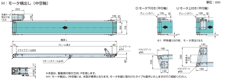
Dimensions
Estimated payload
The graph below shows the transport mass when a horizontally distributed load is applied at a constant speed.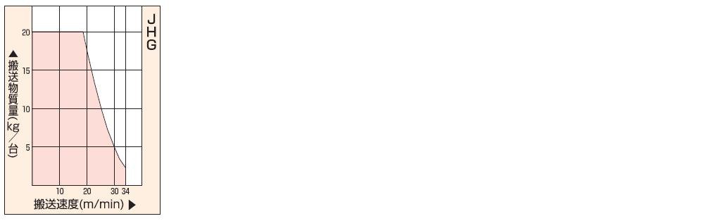
Note) In the case of variable speed models, when the conveying speed drops to 1/3 of the maximum speed, the conveying mass drops to 40% of the maximum speed.
Speed symbol/Conveyor speed table
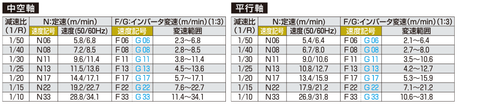
- 1.表は50%負荷時の公称速度を表します。
2.定速及び変速のインバータ方式の速度は、負荷により±10%程度変動します。