HOME > Product Information > Conveyor Equipment > Light Conveyor > Belcon Mini > Belcon Mini Slim Mini / MBM
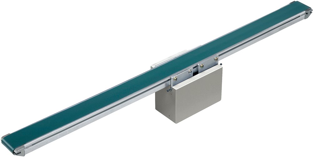
Belcon Mini Slim MiniMBM (Center Drive Standard)
MBG (Center Drive, Snake-Free)
MBM: Center drive standard / MBG: Center drive snake-less
An ultra-compact conveyor ideal for installation in equipment and machinery.


About the various icons
specification
 MBM |
 50 |
 R |
 120 |
 S10 |
 D |
*Colored text is semi-standard.
|
Model code | MBM (Center drive standard) MBG (Center drive serpentine-less) | ||
|---|---|---|---|---|
|
Nominal width | 50 | 75 | 100 |
| BW Actual belt width (mm) | 50 | 75 | 100 | |
| FW Frame width (mm) | 60 | 85 | 110 | |
|
Captain (cm) | MIN.50〜MAX.150 | ||
| Standard Belt | MBM: Resin flat belt (1-ply) MBG: Resin meandering prevention belt with bars (1-ply) | |||
| End Pulley Diameter | MBM: φ17.3 MBG: φ20 | |||
|
Mounting direction of drive unit | R: Right side of conveying direction (standard) L: Left side of conveying direction *Driver board mounting direction | ||
|
Speed symbol | S: 06, 10, 15 Please refer to the "Speed Symbol/Conveyor Speed Table" *Speed selection type | ||
| Motor Output | DC brushless motor (61W) | |||
|
Input Power | D: DC24V (X: AC100V single phase Y: AC200V single phase Z: AC200V three phase) | ||
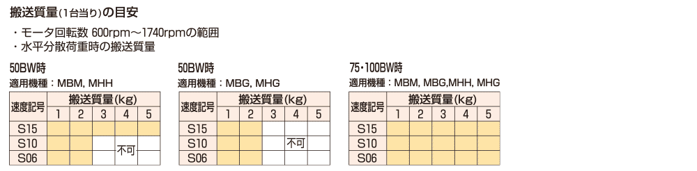
| Transfer mass *1 | MAX.5kg/unit | |||
- Please refer to "Guideline for payload."
Driver board specifications
- Motor: DC24V, 2.55A (rated current)
- Power supply capacity /DC24V 3A or more
- Operating temperature: 0 to 40°C (no condensation)
- Board size: length 106 x height 41 x depth 21 mm
- others /Start/stop acceleration/deceleration time setting function, forward/reverse rotation function, and three speed selections possible from an external signal
(There are some restrictions on selection, so please refer to the "Speed Symbol/Conveyor Speed Table.")
- If you are using it in an AC (alternating current) environment, an optional power supply box (DC conversion box) is available.
- When the power supply box is attached to the conveyor body, it protrudes 60.5 mm in the width direction of the frame. Power supply box dimensions: length 164 x height 40 x depth 60.5 mm
- If the input power supply is three phases, one phase is left out at the input.
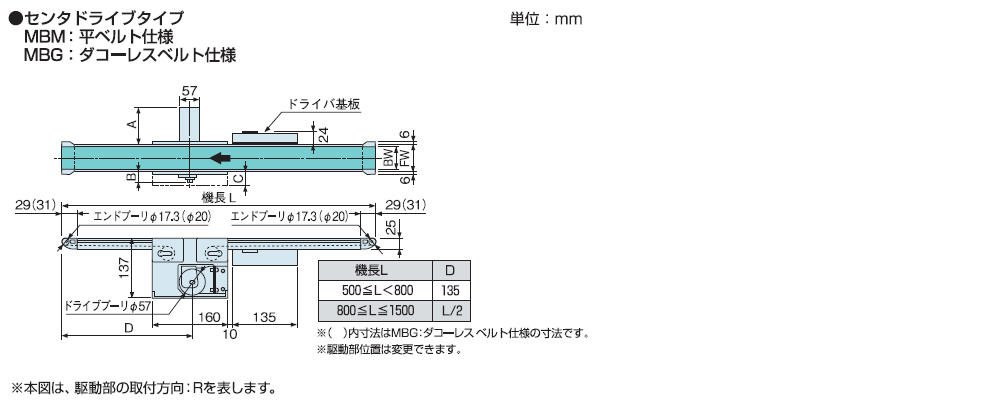
Dimensions
Estimated payload
Speed symbol/Conveyor speed table
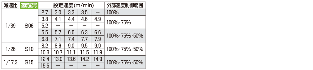
- 1. Change the speed setting using the driver's DIP switch. (You can select a setting speed within the speed symbol range.)
2. Furthermore, speed control of 100%, 75%, or 50% of the set speed is possible using an external input signal. (The external speed control range differs depending on the set speed, so please refer to the table above.)
3. Speed may vary depending on the load.