Belcon MiniENBH
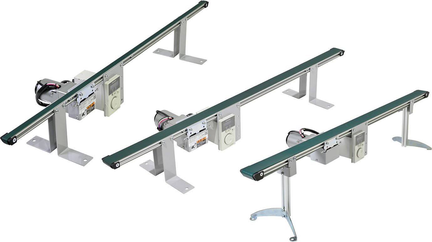
Micro belt conveyor, single row type
An ultra-compact conveyor ideal for installation in equipment and machinery.


About the various icons

specification
 ENBH |
 35 |
 D |
 L |
 80 |
 A18 |
 R |
 006 |
 XP |
*Colored text is semi-standard.
|
Model code | ENBH (center drive flat belt) | |||
|---|---|---|---|---|---|
|
Nominal width | 15 | 35 | 45 | |
| BW Actual belt width (mm) | 15 | 34 | 44 | ||
| FW Frame width (mm) | 20 | 40 | 50 | ||
|
Captain (cm) | 13≦Captain≦100 *For units with a length of 41cm or less, the controller must be placed separately. |
16≦Captain≦100 *For units with a length of 42cm or less, the controller must be placed separately. |
||
| Standard Belt | Resin flat belt (1 ply) | ||||
| End pulley diameter (mm) | φ6 (R3) | φ10 (R5) | |||
|
Drive Type | D: Subscript | |||
|
Mounting direction of drive unit | R: Right side of conveying direction L: Left side of conveying direction | |||
|
Speed symbol | Please refer to the "Speed Symbol/Conveyor Speed Table" | |||
|
Controller installation direction | R: Right side of conveying direction L: Left side of conveying direction S: Separate | |||
|
Motor Output | 006: 6W | |||
|
Input Power | XP: 100V single-phase power cord 2m with plug YT: 200V single-phase power cord 2m (no plug) YP: 200V single-phase power cord, 3m with plug |
|||
| Machine height (mm) | 130≦Machine height≦500 | ||||
| Conveying direction | Forward or reverse operation (forward and reverse operation is not possible) | ||||
| Transfer mass *1 | 1kg/unit | 2kg/unit | |||
- horizontal distributed load
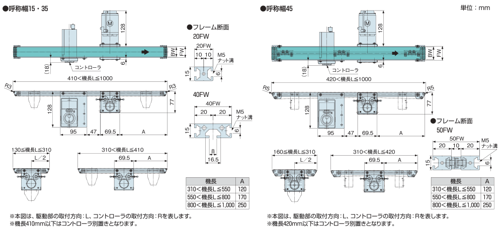
Dimensions
Speed symbol/Conveyor speed table

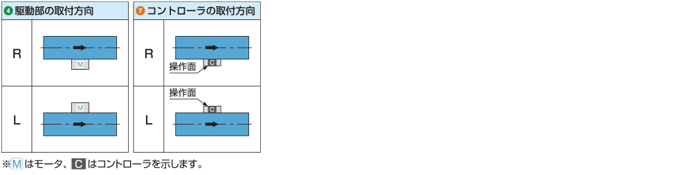
Drive unit installation direction/controller installation direction
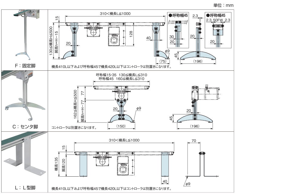
Legs for ENBH [ENSH]

Speed controller for micro belt conveyor
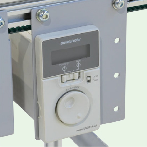
- This is a dedicated controller for operating the variable speed motor (6W, 15W) dedicated to the micro belt conveyor.
- The primary power supply specification can be selected from single-phase 100V or single-phase 200V (three-phase 200V specification is not available).
- The dedicated motor and controller are connected with a dedicated connector, making it easy to replace parts in the event of a malfunction.
- The operation switch on the controller panel can be used to operate the unit on/off (by changing parameters, operation/stop control via external signals is also possible).
- The speed can be set using the dial on the controller panel.
- The display on the controller panel shows the rotation speed, alarm code, etc.
- The acceleration/deceleration time can be set using the acceleration/deceleration time setting switch on the back of the panel (settable time: 0.1 to 15.0 seconds. Default value: 1.0 seconds).
- Equipped with alarm detection functions (motor protection functions) for motor overheating, motor lock, motor connection failure, etc. (An alarm signal cannot be output externally when an alarm occurs.)
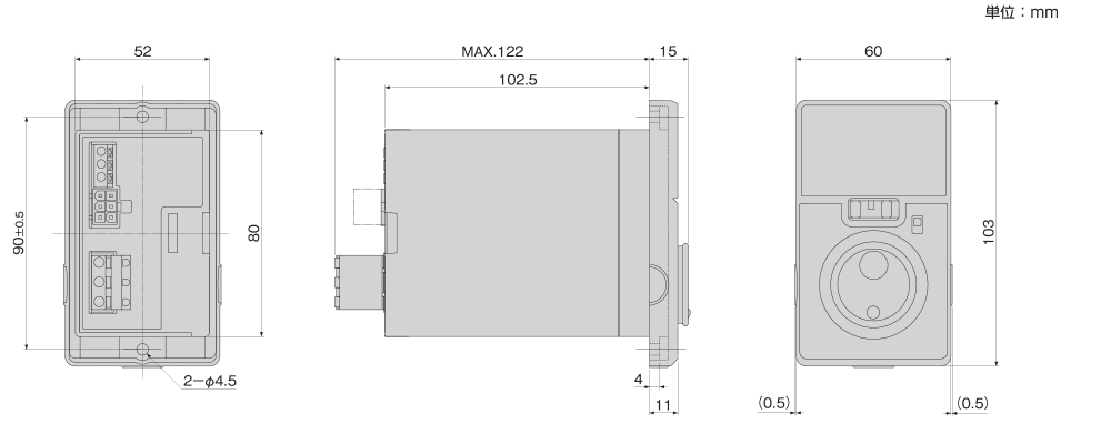
Dimensions
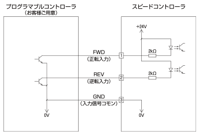
Standard wiring diagram (when using external signals)
When using a programmable controller to control operation/stop from an external signal, you can change the parameters and connect it to the input signal terminal as shown in the diagram below for control (this controller has input signal terminals but no output signals).