Wheel Conveyor
- Lineup
- Functions and application examples
Selection
① Checking the transported items and working environment
The conditions for conveyed materials are even more restrictive than those for Roller Conveyor, so please pay close attention and confirm them carefully. Otherwise, the selection process is generally the same as for Roller Conveyor.
① Conditions of transported goods
- External dimensions (length, width, height) and flow direction.
- Mass per unit (maximum and minimum if multiple types are used).
- The shape and material of the transported items, such as cardboard cases, plastic cases, wooden boxes, etc.
- Condition of the bottom surface (pay attention to unevenness and protrusions)
② Conveyance amount conditions
- Are the items packed tightly together on the conveyor, or are they spaced apart at an appropriate distance?
③ Working conditions
- Either room temperature, high temperature, or low temperature.
- How much water and humidity is there?
④ Loading conditions
- How to load items onto the conveyor?
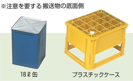
② Width selection
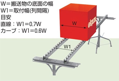
Select the width of the abacus conveyor and the row spacing of the roller carriers according to the external dimensions of the transported items.
① Abacus conveyor
- The width should be at least 50mm larger than the width of the bottom of the item being transported.
② Colocon carrier
- The row spacing should be 0.6 to 0.7 times the width of the bottom of the transported items.
- The row spacing can only be adjusted for straight rows, not curved rows.
- The approximate width of the transported items that can be transported within the row spacing adjustment range is 160 to 750 mm.
③ Wheel type selection
Select the wheel model that best suits your operating conditions, taking into account the wheel's characteristics. (When using Corocon wheels on a frame other than the standard frame, also consider the wheel's strength.)
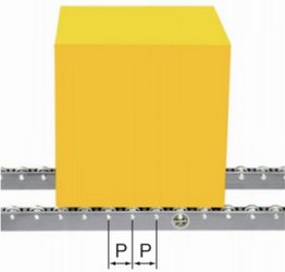
④ Wheel pitch selection
Always make sure that each row of transported goods is supported by at least four wheels. Also, make sure that the load on each wheel is below the allowable load.
⑤ Selecting the leg mounting pitch
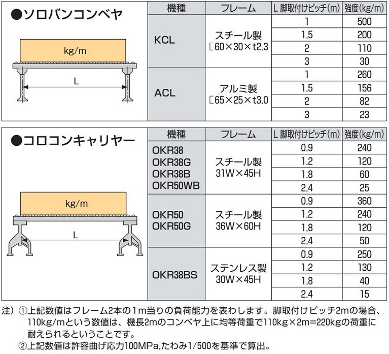
As a guideline, one leg should be installed every 1,800 mm on straight sections. Intermediate legs are always required on curved sections. For details, refer to the "Strength table for two frames." Convert the mass of the transported item into mass per m and select a leg installation pitch that is equal to or less than the allowable load.
Strength table for two frames
⑥ Guide to selecting the self-propelled gradient (incline angle)
The self-propelled gradient will vary depending on the condition of the bottom surface of the transported object, the material, and the weight, but please refer to the table below as a rough guide.
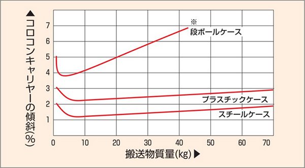
*If the bottom surface is made of a soft material such as cardboard, a large amount of material will get stuck in the rollers, causing increased resistance.
Common Specifications
Wheel Conveyor models and standard specifications
| name | Model | wheel | Frame | Captain (L) |
curve (θ) |
Machine height (H) |
Frame Inner Width (FW) |
Features | |||
|---|---|---|---|---|---|---|---|---|---|---|---|
| material | Outer diameter | Sha Futo |
Pitch (P) | ||||||||
| S B B hmm |
KCL | steel | φ38 | φ6 Long Bolt |
75 100 |
 60×30×t2.3 |
500 1,000 1,500 2,000 2,500 3,000 |
30° 45° 60° 90° |
67 | 250 315 400 500 |
Standard steel type for light loads. |
| ACL | aluminum | φ50 | 65×25×t3.0 |
45° 90° | 76 | 250 315 400 |
Portable aluminum type. | ||||
| name | Model | wheel | Frame | Captain (L) |
curve (θ) |
Machine height (H) |
Two columns Between rows size (W1) |
Features | |||
|---|---|---|---|---|---|---|---|---|---|---|---|
| material | Outer diameter | shaft | Pitch (P) | ||||||||
| Ko B Ko hmm tree A R Ya | |
OKR38 | steel | φ38 | M6 bolt |
50 75 100 150 |
straight 31W x 45H curve  36W x 43H |
1,800 2,400 |
90° | 53 | 115 230 340 450 |
Standard steel type for light loads. |
| OKR38G | steel (rubber lining) |
φ42 | 55 | The rubber lining prevents damage to the bottom of the transported items. | |||||||
| OKR38B | resin | φ38 | 53 | Resin wheel type. | |||||||
| OKR50 | steel | φ50 | 75 100 150 |
straight36W x 60H curve 41W x 55H |
68 | This is an enhanced version of OKR38. | |||||
| OKR50G | steel (rubber lining) |
φ55 | 70.5 | The rubber lining prevents damage to the bottom of the transported items. | |||||||
| OKR50WB | steel | φ50 | 60 100 |
straight31W x 45H curve 31W x 43H |
58 | The wide wheels allow for stable transport of transported items. | |||||
| OKR38BS | resin | φ38 | 50 75 100 150 |
straight 30W x 45H curve  31W x 45H |
53 | 110 220 330 440 |
This type has a stainless steel frame with plastic wheels. | ||||
Part names
Soroban conveyor
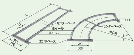
FW = Frame internal width, Machine width = (Steel frame: FW+60, Aluminum frame: FW+50), L = Machine length, H = Machine height, P = Wheel pitch, θ = Curve angle, Leg mounting holes (Steel frame: φ9, Aluminum frame: φ8.5)
Corocon Carrier
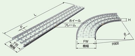
W1 = row spacing L = aircraft length H = aircraft height P = wheel pitch θ = curve angle Center R = central curve radius W1 = 115 (110), 230 (220), 340 (330), 450 (440), ( ) is OKR38BS
*The basic unit for the Corocon carrier is one row, but it is generally used in two rows. The two-row and three-row types have end bases built in, and the 2,400mm long model also has a center base built in.
Soroban conveyor wheel arrangement pattern

Paint color
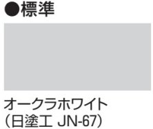
Installing the roller carrier (does not apply to OKR38BS)
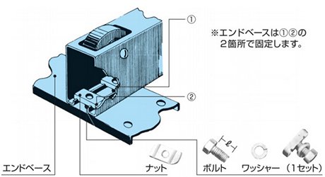
Corocon mounting bolts
| wheel | Model | Bolt dimensions | Purpose |
|---|---|---|---|
| Common for 38 type and 50 type | OKR16BN | M8×16ℓ | For straight |
| OKR20BN | M8×20ℓ | For curves |
Number of roller bearing mounting bolts
| Captain Curve Angle |
number of columns | ||
|---|---|---|---|
| 2 rows | 3 rows | ||
| straight | 1,800mm | 8 pieces | 12 pieces |
| 2,400mm | 10 pieces | 15 pieces | |
| curve | 90° | ||
Connecting fittings

Application example
- Supermarket distribution center
-
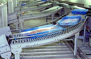
In the sorting chute
- Vegetable sorting facility
-
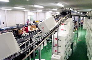
For empty box conveying lines
- Katsura Factory
-
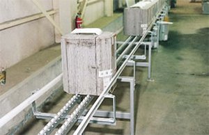
On the conveyor line
- Packaging materials logistics center
-
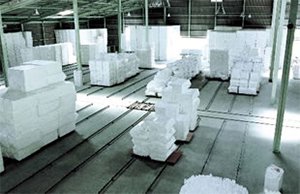
For storage lines of bulky products
- Magazine distribution center
-
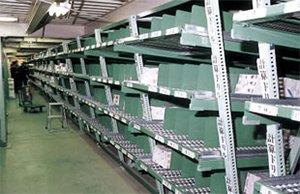
Flowrack® ("Flowrack" is a registered trademark of Okura Yusoki)